
U-Boot: Understanding lowlevel_init
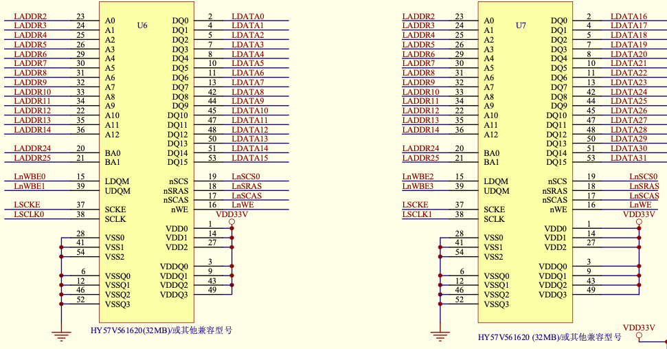
MINI2440 has two SDRAM chips on board, different version have different chipset, my SDRAM is EM63A165TS-6G from EtronTech, the pin and timing is compatible with HY57V561620.
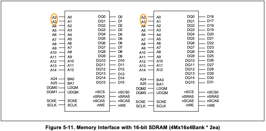
Memory Interface with SDRAM
According to S3C2440 spec, for 16-bit SDRAM the pin A[3:2] should be connected to SoC’s A[1:0]:
The address range can be determined with the following table:
Table 5-1. Bank 6/7 Addresses
| Address(bank6) | 2MB | 4MB | 8MB | 16MB | 32MB | 64MB | 128MB |
|---|---|---|---|---|---|---|---|
| Start address | 0x3000_0000 | 0x3000_0000 | 0x3000_0000 | 0x3000_0000 | 0x3000_0000 | 0x3000_0000 | 0x3000_0000 |
| End address | 0x301F_FFFF | 0x303F_FFFF | 0x307F_FFFF | 0x30FF_FFFF | 0x31FF_FFFF | 0x33FF_FFFF | 0x37FF_FFFF |
| Address(bank7) | 2MB | 4MB | 8MB | 16MB | 32MB | 64MB | 128MB |
|---|---|---|---|---|---|---|---|
| Start address | 0x3020_0000 | 0x3040_0000 | 0x3080_0000 | 0x3100_0000 | 0x3200_0000 | 0x3400_0000 | 0x3800_0000 |
| End address | 0x303F_FFFF | 0x307F_FFFF | 0x30FF_FFFF | 0x31FF_FFFF | 0x33FF_FFFF | 0x37FF_FFFF | 0x3FFF_FFFF |
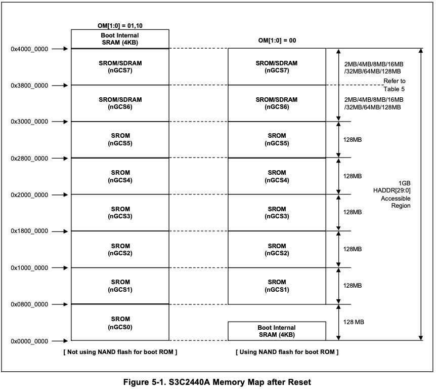
The memory map after reset as follows:
Setup SDRAM Timing
For SDRAM working properly, the timing requirement should be fulfilled, below is a list terms regarding the timing parameters:
| Terms | Description |
|---|---|
| RAS | row address strobe |
| CAS | column address strobe |
| nSRAS | SDRAM row address strobe |
| nSCAS | SDRAM column address strobe |
| SCAN | Column address number |
| CBR | CAS before RAS refresh |
| Trcd | RAS to CAS delay |
| Trp | SDRAM RAS pre-charge Time |
| Tsrc | SDRAM Semi Row cycle time Tsrc = Trc - Trp |
| Trc | SDRAM Row cycle time Trc = Tsrc + Trp |
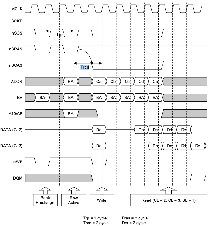
The following SDRAM timing diagram can help understanding these terms:
Set Bus Width
Bus width is controlled by BWSCON register, as our SDRAMs are connected to nGCS6, we only care about setting bus width for the last two banks, the bit definition for BUS WIDTH & WAIT CONTROL REGISTER (BWSCON) are as follows:
| Register | Address | R/W | Description | Reset Value |
|---|---|---|---|---|
| BWSCON | 0x48000000 | R/W | Bus width & wait status control register | 0x000000 |
| BWSCON | Bit | Description | Initial state |
|---|---|---|---|
| ST7 | [31] | Determines SRAM for using UB/LB for bank 7. 0 = Not using UB/LB (The pins are dedicated nWBE[3:0]) 1 = Using UB/LB (The pins are dedicated nBE[3:0]) |
0 |
| WS7 | [30] | Determines WAIT status for bank 7. 0 = WAIT disable 1 = WAIT enable |
0 |
| DW7 | [29:28] | Determines data bus width for bank 7. 00 = 8-bit 01 = 16-bit, 10 = 32-bit 11 = reserved |
0 |
| ST6 | [27] | Determines SRAM for using UB/LB for bank 6. 0 = Not using UB/LB (The pins are dedicated nWBE[3:0 ) 1 = Using UB/LB (The pins are dedicated nBE[3:0]) |
0 |
| WS6 | [26] | Determines WAIT status for bank 6. 0 = WAIT disable, 1 = WAIT enable |
0 |
| DW6 | [25:24] | Determines data bus width for bank 6. 00 = 8-bit 01 = 16-bit, 10 = 32-bit 11 = reserved |
0 |
Here the bus width are set to 32-bit:
#define BWSCON	0x48000000

/* BWSCON */
#define DW8			(0x0)
#define DW16			(0x1)
#define DW32			(0x2)
#define WAIT			(0x1<<2)
#define UBLB			(0x1<<3)

#define B6_BWSCON		(DW32)
#define B7_BWSCON		(DW32)
Bank Control
BANK CONTROL REGISTER (BANKCONn: nGCS6-nGCS7) define the following parameters:
| Register | Address | R/W | Description | Reset Value |
|---|---|---|---|---|
| BANKCON6 | 0x4800001C | R/W | Bank 6 control register | 0x18008 |
| BANKCON7 | 0x48000020 | R/W | Bank 7 control register | 0x18008 |
| BANKCONn | Bit | Description | Initial State |
|---|---|---|---|
| MT | [16:15] | Determine the memory type for bank6 and bank7. 00 = ROM or SRAM, 01 = Reserved 10 = Reserved, 11 = Sync. DRAM |
11 |
| Trcd | [3:2] | RAS to CAS delay 00 = 2 clocks 01 = 3 clocks 10 = 4 clocks |
10 |
| SCAN | [1:0] | Column address number 00 = 8-bit 01 = 9-bit 10 = 10-bit |
00 |
To setup above correctly, consult to the SDRAM datasheet is required:
- The memory type is Synchronous DRAM (SDRAM), so the MT=0x3
- Column Address is A0-A8, so
SCAN= 0x1 - tRCD = 18 ns, SDRAM using HCLK which is 101.25 MHz, so the Trcd = (18ns * HCLK) / 1000 = 1.822, clk = 2clk
Table 16. Electrical Characteristics and Recommended A.C. Operating Conditions
| Symbol | A.C. Parameter Min. | EM63A165TS-6 | |
|---|---|---|---|
| tRCD | RAS# to CAS# delay (same bank) | 18 (min) | - (max) |
| tRP | Precharge to refresh/row activate command (same bank) | 18 (min) | - (max) |
| tRC | Row cycle time (same bank) | 60 (min) | - (max) |
Set both bank 6 and 7 with same paramters:
/* BANK6CON */
#define B6_MT			0x3	/* SDRAM */
#define B6_Trcd			0x0	/* 2clk */
#define B6_SCAN			0x1	/* 9bit */

/* BANK7CON */
#define B7_MT			0x3	/* SDRAM */
#define B7_Trcd			0x0	/* 2clk */
#define B7_SCAN			0x1	/* 9bit */
Refresh Parameters
The remaining are SDRAM refresh related, the REFRESH CONTROL REGISTER bit definition as follows:
| Register | Address | R/W | Description | Reset Value |
|---|---|---|---|---|
| REFRESH | 0x48000024 | R/W | SDRAM refresh control register | 0xac0000 |
| REFRESH | Bit | Description | Initial State |
|---|---|---|---|
| REFEN | [23] | SDRAM Refresh Enable 0 = Disable 1 = Enable (self or CBR/auto refresh) |
1 |
| TREFMD | [22] | SDRAM Refresh Mode 0 = CBR/Auto Refresh 1 = Self Refresh In self-refresh time, the SDRAM control signals are driven to the appropriate level. |
0 |
| Trp | [21:20] | SDRAM RAS pre-charge Time 00 = 2 clocks 01 = 3 clocks 10 = 4 clocks 11 = Not support |
10 |
| Tsrc | [19:18] | SDRAM Semi Row cycle time 00 = 4 clocks 01 = 5 clocks 10 = 6 clocks 11 = 7 clocks SDRAM Row cycle time: Trc=Tsrc+Trp If Trp = 3clocks & Tsrc = 7clocks, Trc = 3+7=10clocks. |
11 |
| Reserved | [17:16] | Not used | 00 |
| Reserved | [15:11] | Not used | 0000 |
| Refresh Counter | [10:0] | SDRAM refresh count value. Refer to chapter 6 SDRAM refresh controller bus priority section. Refresh period = (211-refresh_count+1)/HCLK e.g. If refresh period is 7.8 us and HCLK is 100MHz, the refresh count is as follows: Refresh count = 211 + 1 - 100x7.8 = 1269 |
0 |
- Refresh is always enabled
- Us CBR/Auto Refresh
- Trp is same as Trcd = 18ns = 2clk
- Tsrc = Trc - Trp = (60 - 18) = 42ns = (42ns * HCLK) / 1000 = 4.2525clk = 5clk
- Refresh count = 211 + 1 - HCLK * refresh period
Refresh count = 211 + 1 - 101.25 * 7.8125 = 2049 - 791 = 1258
Refresh period = 64ms / 8192 refresh cycles
Put above REFRESH parameters to code is:
#define REFEN			0x1	/* Refresh enable */
#define TREFMD			0x0	/* CBR(CAS before RAS)/Auto refresh */
#define Trp			0x0	/* 2clk */
#define Tsrc			0x1	/* 5clk */
#define REFCNT			1258	@ period=7.8125us, HCLK=101.25Mhz, (2048+1-7.8125x101.25)
Banksize and Mode Register Set
Banksize register bit definition as follows:
| Register | Address | R/W | Description | Reset Value |
|---|---|---|---|---|
| BANKSIZE | 0x48000028 | R/W | Flexible bank size register | 0x0 |
| BANKSIZE | Bit | Description | Initial State |
|---|---|---|---|
| BURST_EN | [7] | ARM core burst operation enable. 0 = Disable burst operation. 1 = Enable burst operation. |
0 |
| Reserved | [6] | Not used | 0 |
| SCKE_EN | [5] | SDRAM power down mode enable control by SCKE 0 = SDRAM power down mode disable 1 = SDRAM power down mode enable |
0 |
| SCLK_EN | [4] | SCLK is enabled only during SDRAM access cycle for reducing power consumption. When SDRAM is not accessed, SCLK becomes ‘L’ level. 0 = SCLK is always active. 1 = SCLK is active only during the access (recommended). |
0 |
| Reserved | [3] | Not used | 0 |
| BK76MAP | [2:0] | BANK6/7 memory map 000 = 32M/32M 001 = 64MB/64MB 010 = 128MB/128MB 111 = 16M/16M 101 = 4M/4M 110 = 8M/8M 100 = 2M/2M |
010 |
The banksize register setup as follows:
- Enable burst operation
- Enbale power down mode
- SCLK enabled
- Bank6 is 64 MB
So the value for bank size register is 0b1011_0001(0xB1).
SDRAM MODE REGISTER SET REGISTER (MRSR)
| Register | Address | R/W | Description | Reset Value |
|---|---|---|---|---|
| MRSRB6 | 0x4800002C | R/W | Mode register set register bank6 | xxx |
| MRSRB7 | 0x48000030 | R/W | Mode register set register bank7 | xxx |
| MRSR | Bit | Description | Initial State |
|---|---|---|---|
| Reserved | [11:10] | Not used | - |
| WBL | [9] | Write burst length 0: Burst (Fixed) 1: Reserved |
x |
| TM | [8:7] | Test mode 00: Mode register set (Fixed) 01, 10 and 11: Reserved |
xx |
| CL | [6:4] | CAS latency 000 = 1 clock, 010 = 2 clocks, 011=3 clocks Others: reserved |
xx |
| BT | [3] | Burst type 0: Sequential (Fixed) 1: Reserved |
x |
| BL | [2:0] | Burst length 000: 1 (Fixed) Others: Reserved |
xxx |
NOTE: MRSR register must not be reconfigured while the code is running on SDRAM.
IMPORTANT NOTE: In sleep mode, sdram has to enter sdram self-refresh mode.
For this register most of the bits are set to non-reserved value except for CAS latency, which can be found in SDRAM datasheet, the CL for mini2440 is 2 or 3 clk, so the final set for MRSR is 0x20/0x30.
- CAS Latency: 2, or 3
- Burst Length: 1, 2, 4, 8, or full page
Configuring Registers
To understand the following part, you need to know what literal pool is, the LTORG directive is used to instruct the assembler to assemble the current literal pool immediately, and make processor not attempt to execute the constants as instructions. We use literal pools to store SDRAM related configurations:
	.ltorg

SMRDATA:
    .word (0+(B1_BWSCON<<4)+(B2_BWSCON<<8)+(B3_BWSCON<<12)+(B4_BWSCON<<16)+(B5_BWSCON<<20)+(B6_BWSCON<<24)+(B7_BWSCON<<28))
    .word ((B0_Tacs<<13)+(B0_Tcos<<11)+(B0_Tacc<<8)+(B0_Tcoh<<6)+(B0_Tah<<4)+(B0_Tacp<<2)+(B0_PMC))
    .word ((B1_Tacs<<13)+(B1_Tcos<<11)+(B1_Tacc<<8)+(B1_Tcoh<<6)+(B1_Tah<<4)+(B1_Tacp<<2)+(B1_PMC))
    .word ((B2_Tacs<<13)+(B2_Tcos<<11)+(B2_Tacc<<8)+(B2_Tcoh<<6)+(B2_Tah<<4)+(B2_Tacp<<2)+(B2_PMC))
    .word ((B3_Tacs<<13)+(B3_Tcos<<11)+(B3_Tacc<<8)+(B3_Tcoh<<6)+(B3_Tah<<4)+(B3_Tacp<<2)+(B3_PMC))
    .word ((B4_Tacs<<13)+(B4_Tcos<<11)+(B4_Tacc<<8)+(B4_Tcoh<<6)+(B4_Tah<<4)+(B4_Tacp<<2)+(B4_PMC))
    .word ((B5_Tacs<<13)+(B5_Tcos<<11)+(B5_Tacc<<8)+(B5_Tcoh<<6)+(B5_Tah<<4)+(B5_Tacp<<2)+(B5_PMC))
    .word ((B6_MT<<15)+(B6_Trcd<<2)+(B6_SCAN))
    .word ((B7_MT<<15)+(B7_Trcd<<2)+(B7_SCAN))
    .word ((REFEN<<23)+(TREFMD<<22)+(Trp<<20)+(Tsrc<<18)+REFCNT)
    .word 0x32
    .word 0x30
    .word 0x30
The values calculated for each register as follows:
00000704 <SMRDATA>:
 704:	2211d120 	.word	0x2211d120
 708:	00000700 	.word	0x00000700
 70c:	00000700 	.word	0x00000700
 710:	00000700 	.word	0x00000700
 714:	00001f4c 	.word	0x00001f4c
 718:	00000700 	.word	0x00000700
 71c:	00000700 	.word	0x00000700
 720:	00018001 	.word	0x00018001
 724:	00018001 	.word	0x00018001
 728:	008404ea 	.word	0x008404ea
 72c:	000000b1 	.word	0x000000b1
 730:	00000030 	.word	0x00000030
 734:	00000030 	.word	0x00000030
Now, let’s break down the final part of lowlevel_init:
.globl lowlevel_init                @ called in start.S, make it global
lowlevel_init:
    ldr     r0, =SMRDATA            @ r0 = 0x704
    ldr	r1, =CONFIG_SYS_TEXT_BASE   @ r1 = 0x0
    sub	r0, r0, r1

    ldr	r1, =BWSCON                 @ r1 = 0x48000000
    add     r2, r0, #13*4           @ r2 = 0x738, memory controller have 13 registers in total
0:
    ldr     r3, [r0], #4            @ r3 = 0x2211d120, r0 = 0x708
    str     r3, [r1], #4            @ *(0x48000000) = 0x2211d120, r1 = 0x48000004
    cmp     r2, r0                  @ Compare r2 with r1 and branch to 0b, if r2
                                    @ is not equal to r0 (Z bit in CPSR was set),
                                    @ otherwise continue.
    bne     0b                      @

    mov	pc, lr                      @ return
You can use gdb command x to see if all registers were configured correctly:
>>> x/13 0x48000000
0x48000000:	0x2211d120	0x00000700	0x00000700	0x00000700
0x48000010:	0x00001f4c	0x00000700	0x00000700	0x00018001
0x48000020:	0x00018001	0x008404ea	0x000000b1	0x00000030
0x48000030:	0x00000030
Instructions used in this section are:
| Mnemonic | Instruction | Action |
|---|---|---|
| ADD | Add | Rd: = Rn + Op2 |
| CMP | Compare | CPSR flags: = Rn - Op2 |
| LDR | Load register from memory | Rd: = (address) |
| MOV | Move register or constant | Rd: = Op2 |
| SUB | Subtrace | Rd: = Rn - Op2 |
| STR | Store register to memory | <address>: = Rd |